
Manufacturing Support Fixture
Poka-Yoke Assembly Nest
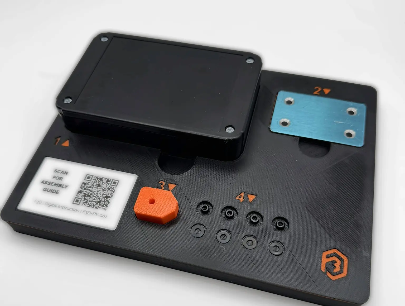
A custom FDM manufacturing-support fixture that turns a loose manual assembly sequence into four defined stations with visible hardware count, keyed orientation, finger-access removal, and a QR-linked digital work instruction.
The challenge
Turn a memory-dependent bench sequence into a controlled physical workflow.
Small manual assemblies become harder to manage when orientation, part order, and hardware count are left entirely to operator memory. Components can be rotated incorrectly, staged out of sequence, omitted, or become difficult to see and retrieve when they are loose on the bench.
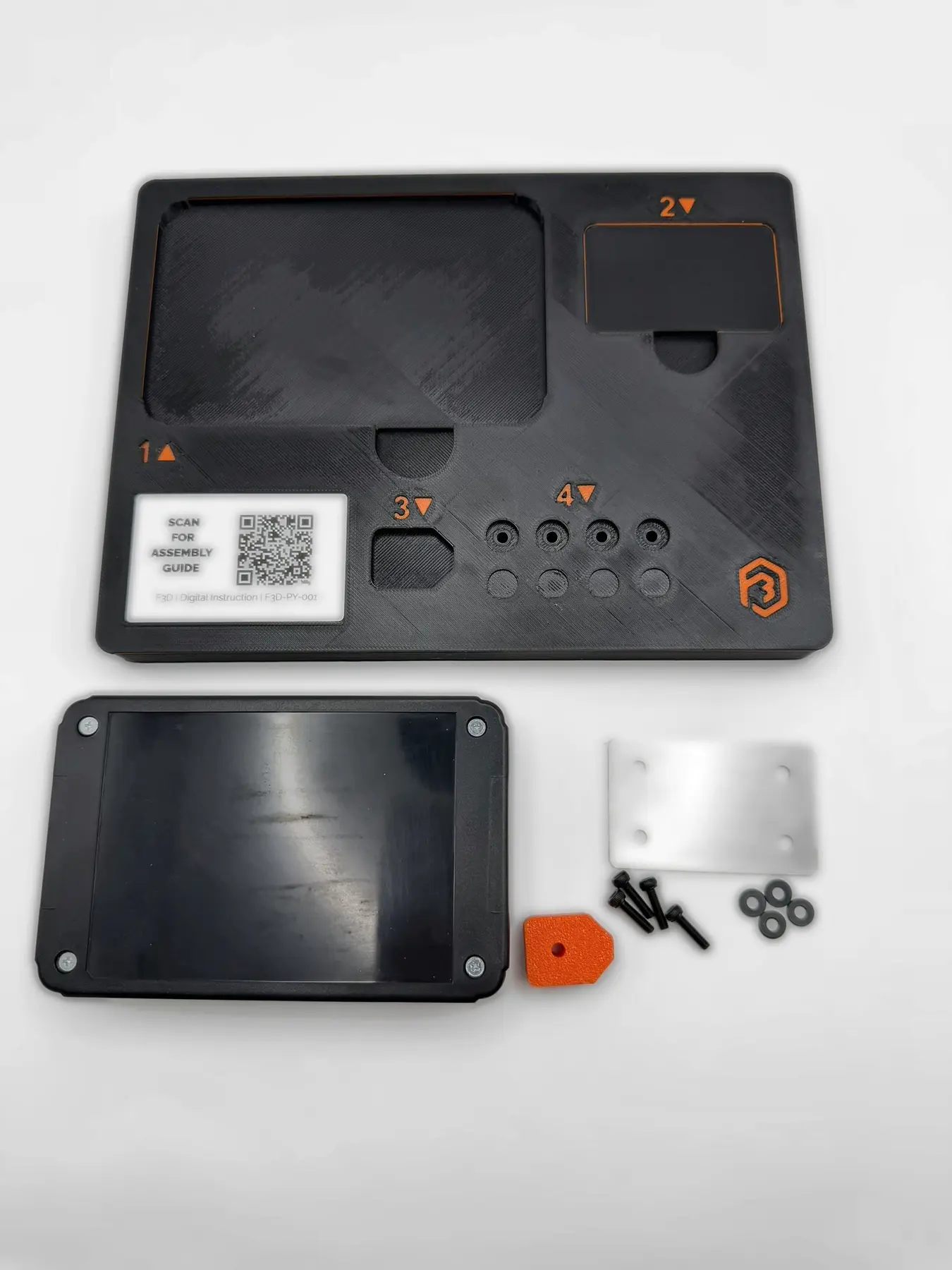
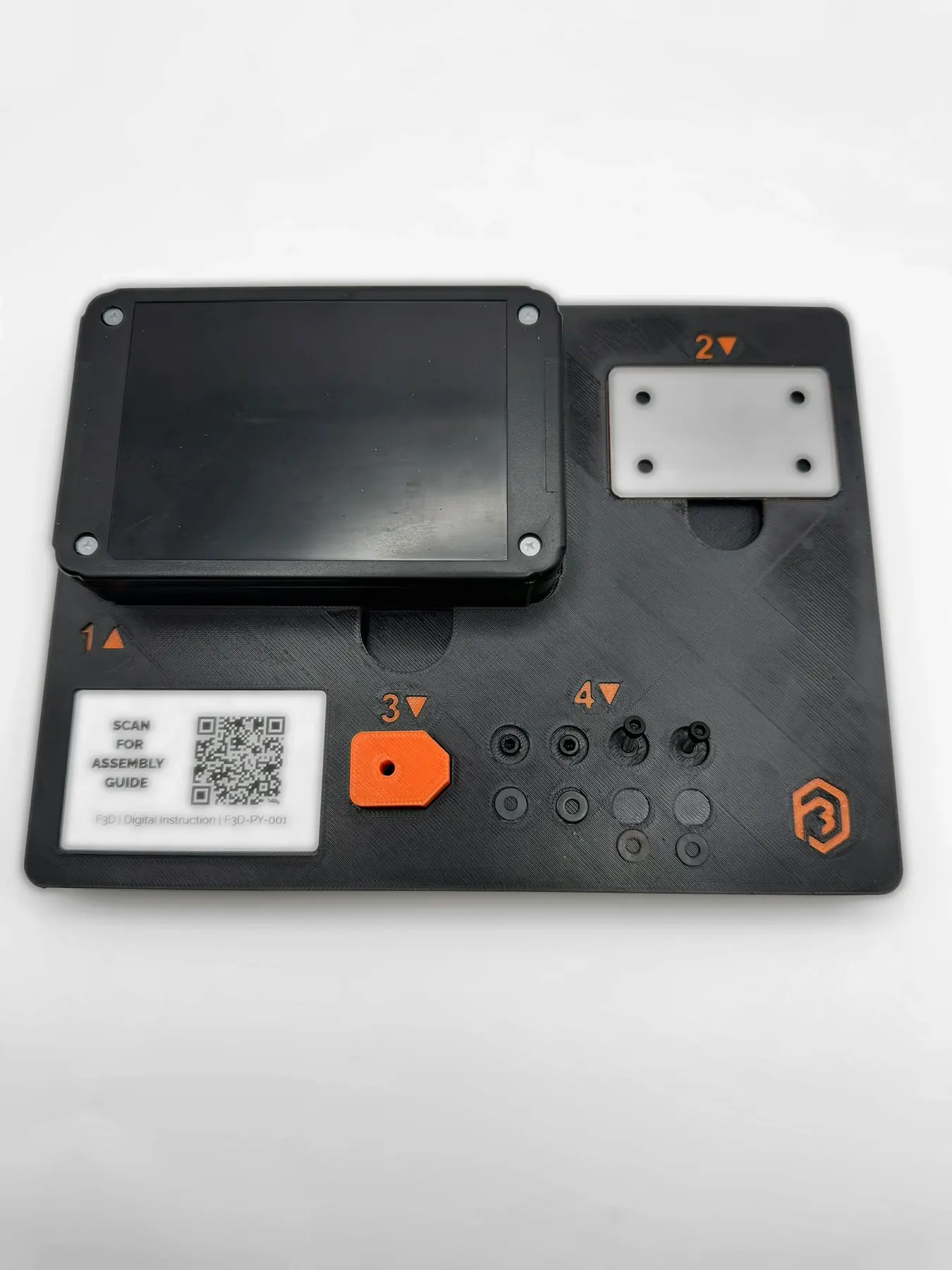
The fixture gives the enclosure, bracket, keyed insert, four screws, and four washers defined locations while keeping every component easy to load and remove by hand.
Controlled interfaces
Requirements locked around the real workflow.
Engineering approach
Use the right level of control at each station instead of forcing one poka-yoke pattern everywhere.
Real reference geometry
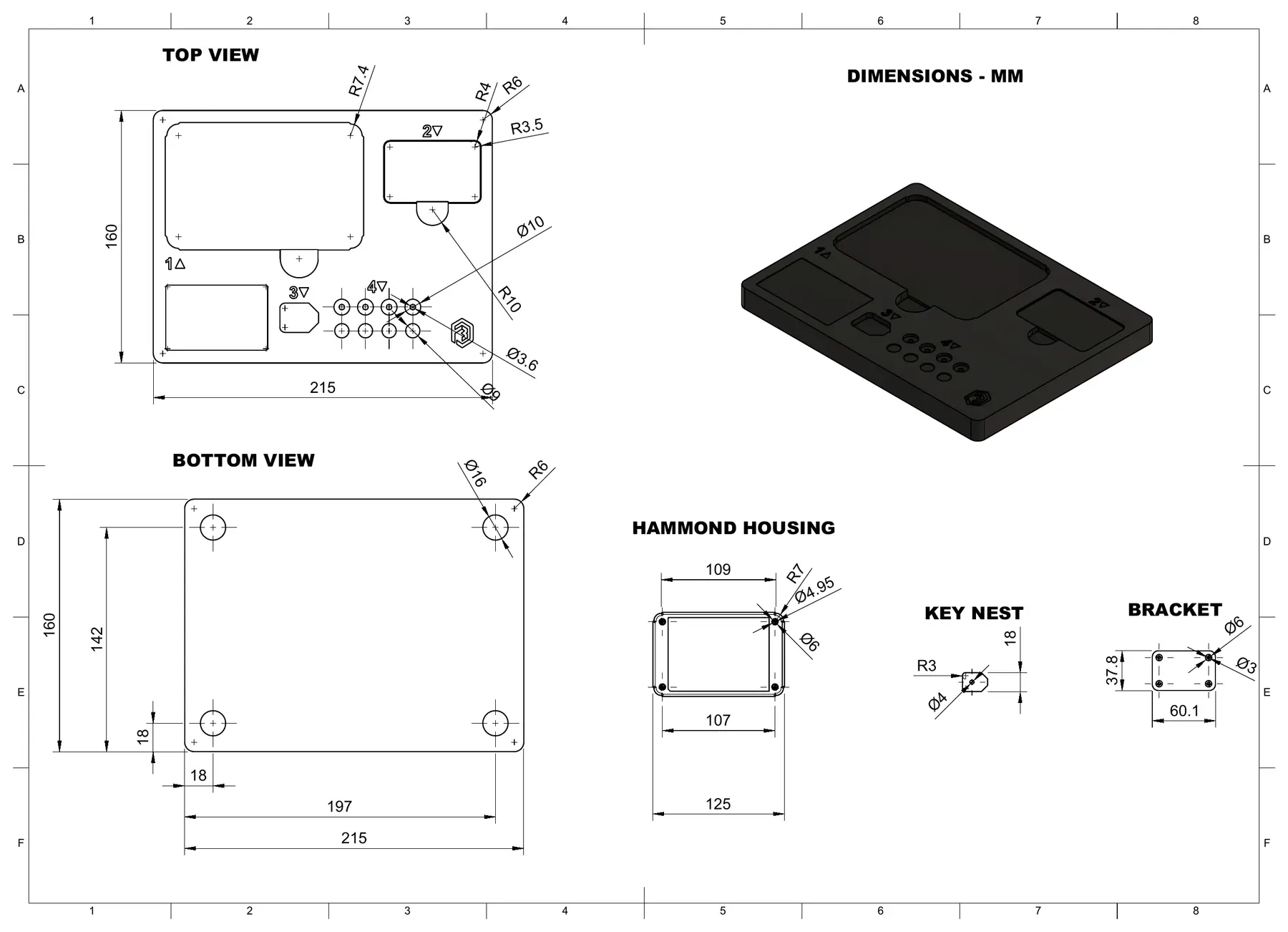
The Hammond enclosure was integrated from manufacturer geometry, while the stainless bracket was measured and physically qualified after arrival.
Mechanical + visual control
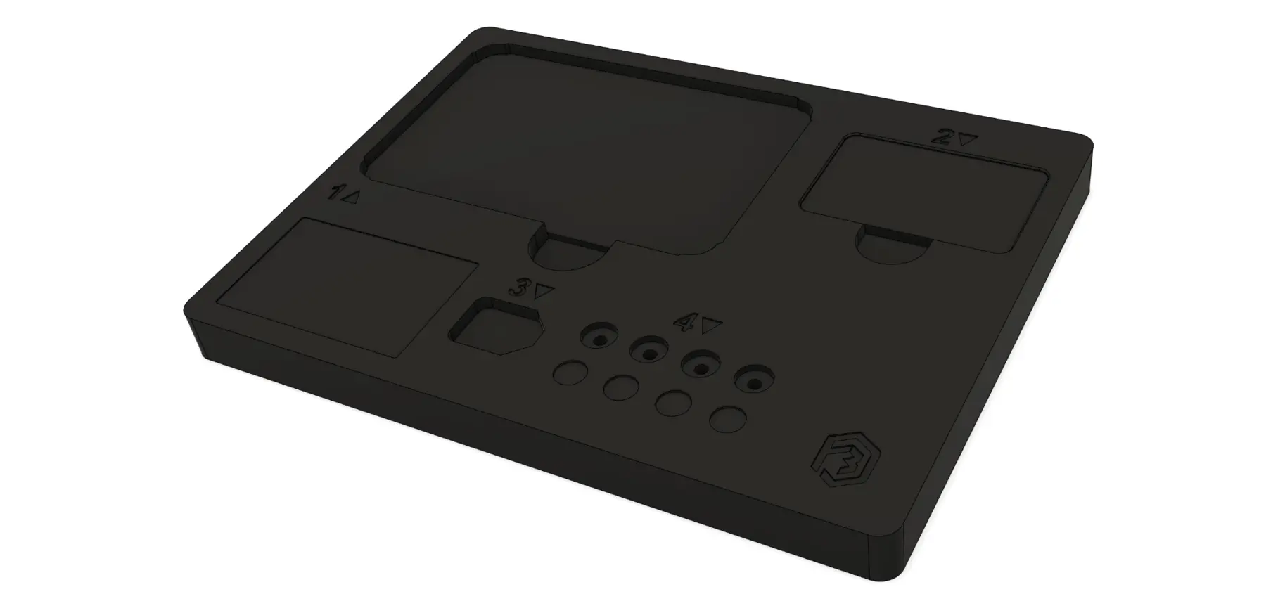
Station 3 uses the strongest keyed profile. Orange numbers, arrows, and defined pockets reinforce the sequence across the remaining stations.
Counted hardware
One dedicated location per screw and washer makes the required hardware count visible before assembly begins.
Digital instruction
A recessed dynamic QR label connects the fixture to F3D-PY-001 so the instruction destination can change without reprinting the part.
Iteration + lessons learned
Rev A proved the concept. Rev B aligned the fixture to real hardware and a cleaner operator workflow.
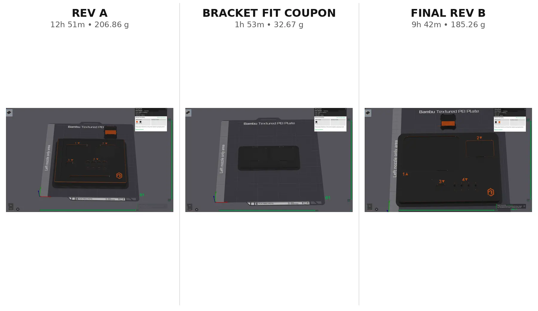
The first complete nest used representative hardware, shallow markings, and a tool channel. The release version replaced those assumptions with real reference components, more readable station markings, and a maintainable QR work instruction.
When the physical bracket would not sit flat, straight-edge clearance was not the problem. A two-pocket coupon isolated the corner radius while holding every other interface constant. R3.5 fit the real stamped bracket and became the production condition.
The final base reduced the print record from 12h 51m and 206.86 g in Rev A to 9h 42m and 185.26 g in Rev B while improving the real component interfaces.
Manufacturing record
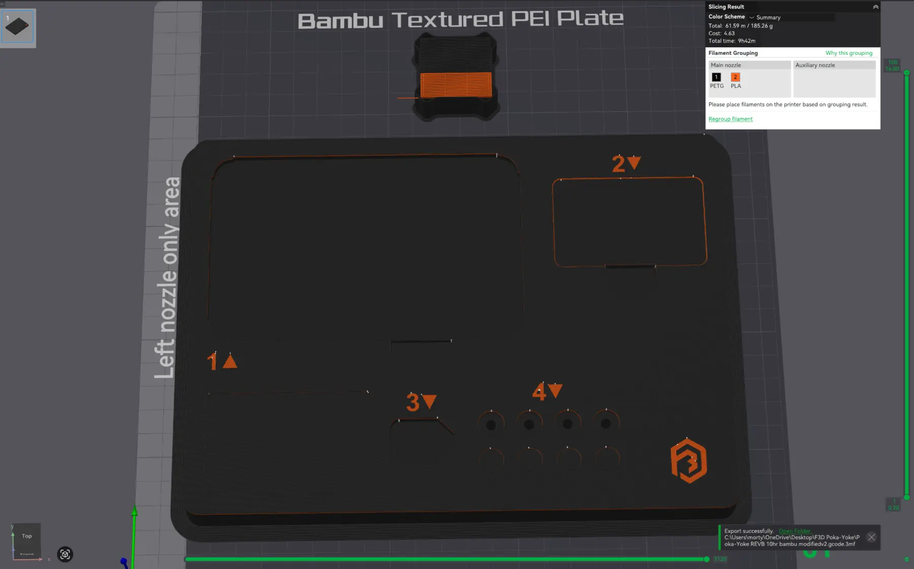
Final sliced data—not superseded revisions.
- Printer / plate
- Bambu Lab X2D / Textured PEI
- Structure
- Black PETG with orange PLA object markings
- Layer / shell
- 0.16 mm; 3 walls; 15% gyroid
- Support / brim
- No support; 7 mm outer brim
- Final time / mass
- 9h 42m / 185.26 g
- Slicer cost record
- $4.63 using active material profiles
The cost shown is a slicer material record, not a customer quote. It excludes labor, equipment, electricity, development coupons, reference hardware, labels, and overhead.
Validation
The physical build passed its intended portfolio checks.
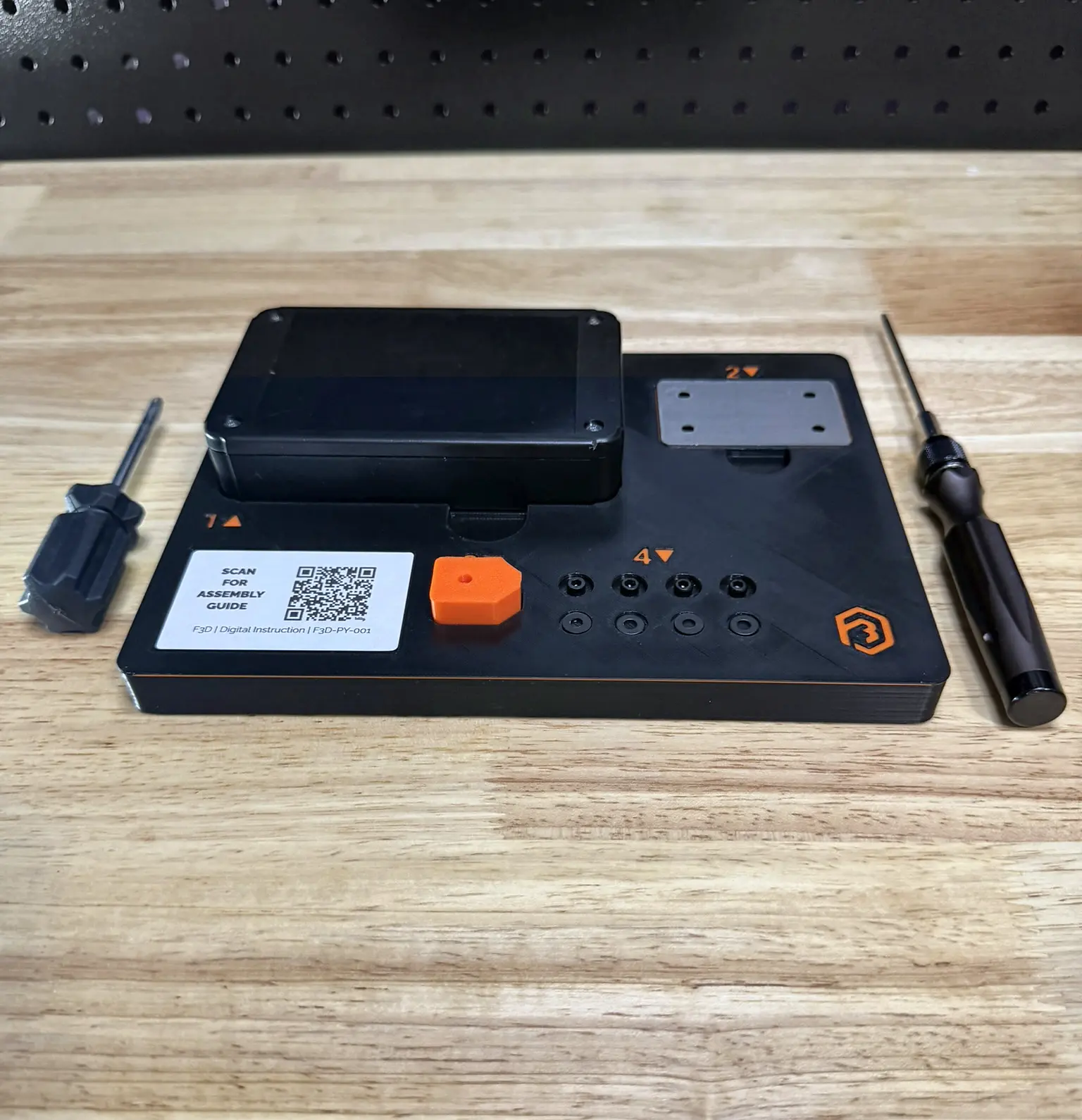
Final base
Printed complete with all stations and hardware wells open.
Enclosure seating
Physical Hammond enclosure seated fully without rocking.
Bracket fit
R3.5 coupon-qualified pocket accepted the real bracket cleanly.
Keyed insert
Asymmetric profile supported the intended orientation.
Hardware count
Four screws and four washers staged visibly in dedicated wells.
Digital instruction
Dynamic QR label opened the current F3D-PY-001 guide.
Business value
What this build actually demonstrates.
The result is not only a printed object. It is evidence of a repeatable path from a practical problem through CAD, focused testing, revision, documented manufacturing, and a physically checked release.
- CAD-assisted fixture design
- Poka-yoke and orientation logic
- Manufacturer-data integration
- Physical measurement and fit coupons
- Counted hardware staging
- QR-linked digital work instructions
- Multi-material object features
- Documented FDM manufacturing
Evidence gallery
Physical, CAD, and dimensional context.
Scope + honest limitations
Prototype evidence without inflated claims.
- Portfolio demonstration, not a customer production tool or OEM work instruction.
- No statistically powered error-rate, takt-time, cycle-life, or capability study was performed.
- No ESD, environmental, chemical, safety, or regulatory qualification was performed.
- The published drawing is visual engineering evidence, not a certified inspection record.
Start with the problem
Does a manual assembly still depend too heavily on memory?
Send the part list, current sequence, available CAD or dimensions, expected quantity, and the step that creates the most inconsistency. The right answer may be a nest, staging fixture, inspection aid, or another purpose-built manufacturing support tool.